|
|
 |
 |
|
Outline
|
Principle of the Alternator
|
|
|
| 2. |
Rectification
|
| (1) |
Mechanism of alternator output rectification. |
 |
Construction
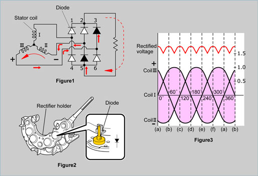
The alternator assembly contains a rectification circuit to rectify the three-phase alternating current by using six diodes, as shown in figure 1. The rectification circuit is built into the rectifier holder, as shown in figure 2. |
| |
Function
As the rotor makes one revolution within the stator coils, electricity is generated in each coil as shown through (a) to (f) in figure 3. In state (a), positive (+) electricity is generated in coil III and negative (-) electricity is generated in the coil II. Therefore, current flows in the direction from coil II to coil III as shown in figure 1.
This current flows into a load via diode 3 and then returns to coil II via the diode 5. At this time, there is no current flowing in coil I.
By the same logic, in states (b) through (f), alternating current is rectified by passing through a pair of diodes and a constant amount of direct current (DC) flows to the electrical load. |
|
|
|
(7)
|
|