|
Click on the bulb mark or the underlined sentence. |
| 3. |
Rectification function
|
| (1) |
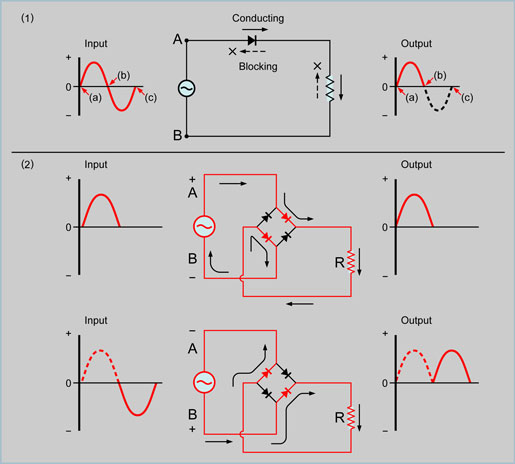
Half-wave rectification |
| (2) |
Full-wave rectification |
|
In this example the AC output from the generator is applied to a group of ordinary rectifying diode that are combined together.
When terminal A of the generator is positive, terminal B is negative, and the current flows as shown in the upper diagram of the illustration (2).
When the polarity at the generator output terminals are reversed, the current flows through the group of diodes as shown in the lower diagram of the illustration (2).
This action allows the output current to always flow in the same direction through resistor “R” and this is known as “full-wave rectification”. |
|
|